WiseShield-32 Soldering Guide
Introduction
Welcome to the WiseShield-32 soldering guide! This manual will walk you through the step-by-step process of assembling your WiseShield-32 PCB. Follow along carefully, and you’ll have your board ready for use in no time!
Before You Start
Tools Required:
- Soldering iron and solder wire
- Wire cutters
- Tweezers
- Desoldering pump (optional but helpful)
- Multimeter (for testing connections)
Tips for Success:
- Always work in a well-ventilated area.
- Use proper ESD precautions to protect sensitive components.
- Double-check component orientation, especially for polarized parts like diodes and capacitors.
- Start with the smallest components and work your way up to larger ones.
Step-by-Step Instructions
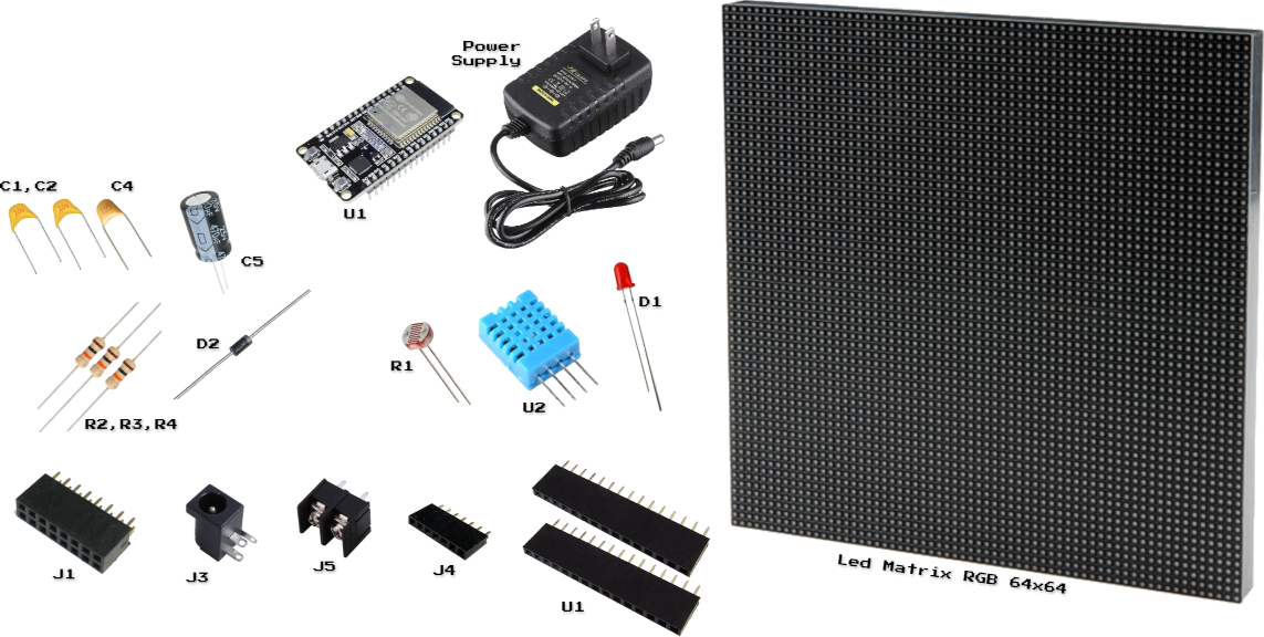
Step 1: Gather and Identify Components
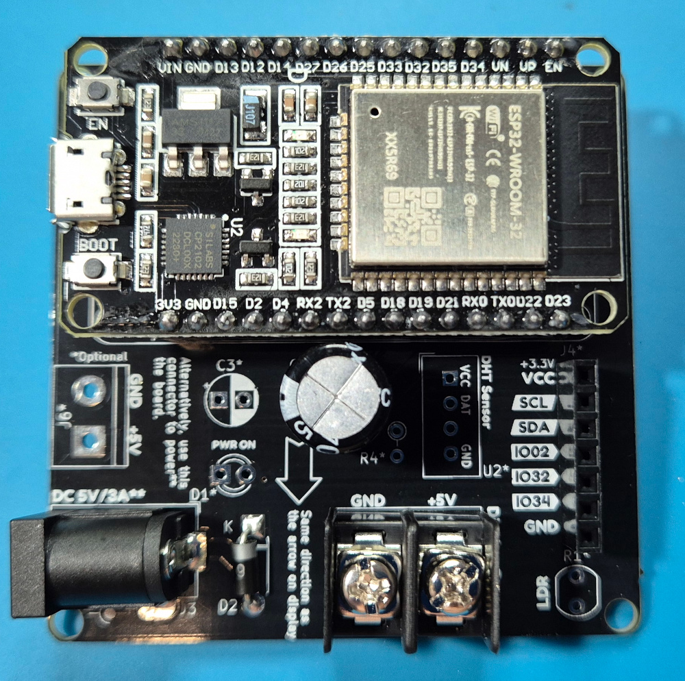
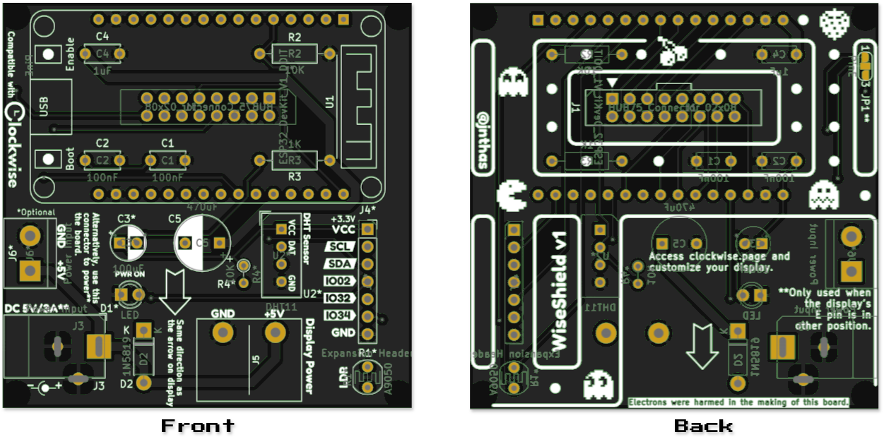
Use the provided labeled PCB image to locate the positions of each component on the board. Match each part with the silkscreen markings (e.g., C1, R2, J1).
Reference Labeled PCB Image:
Base:
- RGB LED Matrix 64x64 + Cables
- ESP32 Dev Board
- AC/DC Power Supply 5V 3A
- WiseShield-32 PCB
Connectors:
- J1 HUB75 Connector
- J3 Barrel Jack Power Supply Connector
- J5 Terminal Block (Display Power)
- J4 7-pin Female Header - Shield Extension
- U1 ESP32 Female Headers (2x15)
Discrete Components:
- C1, C2 Ceramic/Tantalum Capacitor 100nF
- C3 Capacitor 100uF (not included, optional to help stabilize ESP32 voltage input)
- C4 Ceramic/Tantalum Capacitor 1uF
- C5 Electrolytic Capacitor 470uF
- D2 Diode 1N5819
- R2, R3, R4 Resistor 10K
I/O:
- U2 DHT11 Sensor
- R1 LDR 5mm A9050
- D1 LED 3mm
Step 2: Solder the Smallest Components First
- Resistors (R2, R3):
- Function: R2 is a pull-down resistor for the LDR, and R3 limits current for the LED.
- Placement: Refer to the labeled PCB image for exact locations.
- Instructions:
- Insert the resistor leads into the holes.
- Flip the board and bend the leads slightly to hold them in place.
- Solder the leads and trim excess wire.
- Small Capacitors (C1, C2, C4):
- Function: Stabilizes voltage for the ESP32.
- Placement: Near the ESP32 pins and power traces.
- Instructions:
- Insert capacitors, ensuring correct orientation if polarized (e.g., C4).
- Solder and trim the excess leads.
Step 3: Solder Larger Capacitors and Diode
- Large Capacitors (C5):
- Function: Regulate voltage for stability.
- Placement: Near the power input section.
- Instructions:
- Insert capacitors into their positions.
- Align the longer lead (positive) with the “+” marking.
- Solder and trim.
- Diode (D2):
- Function: Blocks reverse current.
- Placement: Near the power input (J3).
- Instructions:
- Align the cathode stripe with the silkscreen marking.
- Solder both leads and trim excess.
Step 4: Add the Connectors
- J3 (Power Input - Barrel Jack):
- Insert and solder the barrel jack connector securely.
- J6 (Power Input - Terminal Block):
- Note: Do not use J3 and J6 simultaneously.
- Insert and solder the terminal block.
- J1 (HUB75 Connector):
- Solder all pins of the 2x8 pin header for the LED matrix connection.
- J5 (Display Power - Terminal Block):
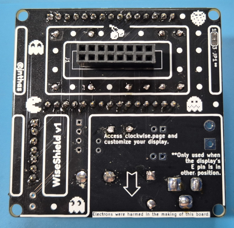
- Attention: J5 is the only connector that is soldered faced to back side.
- Insert and solder securely.
- J4 (Expansion Header - 1x7 Pin):
- Solder the header pins for custom peripherals.
Step 5: Add Peripherals
- LDR (R1):
- Insert the light-dependent resistor and solder it along with R2.
- Indicator LED (D1):
- Insert the LED, ensuring the longer leg (anode) aligns with the “+” marking.
- Solder and trim the leads.
- DHT11 Sensor (U2):
- Insert the temperature and humidity sensor and solder carefully.
Step 6: Prepare the ESP32 DevKit
- Solder the female headers into the ESP32 footprint (U1).
- Plug the ESP32 DevKit into the headers once soldered.
Step 7: Final Inspection
- Inspect all solder joints for:
- Good connections (shiny, smooth).
- No solder bridges between adjacent pads.
- Test connections with a multimeter to verify continuity.
- Clean the PCB with isopropyl alcohol to remove flux residue.
Congratulations!
Your WiseShield-32 is now fully assembled. You’re ready to proceed to the setup stage and start using your Clockwise.